How Do You Use a Multimeter to Check a Circuit for Continuity
Contents
- Multimeter Set Up
- Continuity Testing
- Understanding Circuit Continuity Test Results
- Voltage Test
- Understanding Voltage Test Results
- Resistance Test
- Understanding Resistance Test Results
- Safety Tips
Working in this industry, I learned that a multimeter is vital. One of the most common uses for a multimeter is to test continuity. In case you didn't know, a continuity test is crucial as it checks if a wire or loop on a circuit board is broken.
In general, this is the easiest way to do a continuity check with a multimeter
- Disconnect the device you want to test from a power source. Connect the black probe to your multimeter's COM port. Plug the red into the VΩmA port.
- Configure your multimeter to continuity test mode and turn it on. This usually looks like a sound wave icon.
- Attach one probe to each tip of the circuit or device you are testing.
- Check the results.
Any electrician for DYIR'er should learn how to do a continuity check with a multimeter, which you can use to test electrical components and circuit design in a million different ways. Follow along to learn how to check continuity with a multimeter.
Multimeter Set Up

Shift the multimeter dial to the continuity test function to use the multimeter continuity feature. You should detect an obvious "beep" sound when you touch the multimeter set leads together. Before testing, carefully touch the tips together and listen for the beep. You should do this to ensure that the multimeter continuity feature functions correctly.
Continuity Testing
Checking continuity determines if two objects are electrically connected: if they are, an electric charge can freely pass from one endpoint to the other. (1)
There is a failure somewhere in the wire if there is no continuity. This could be because of a damaged fuse, a poor solder connection, or an improperly wired circuit.
Now, to properly check continuity, follow the steps below:
- Verify that there is no power flowing through the circuit or device you want to test first. Remove any batteries, turn them off, and disconnect them from the wall.
- Connect the black probe to your multimeter's COM port. And, you should insert the red probe into the VΩmA port.
- Configure your multimeter to measure continuity mode and turn it on. This usually looks like a sound wave icon.
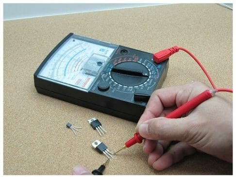
- You should place one probe at each end of the circuit or the device you want to test continuity.
- Then, wait for the results.
Understanding Circuit Continuity Test Results
The multimeter delivers a small amount of current via one probe and sees if the other probe receives it.
It doesn't matter which probe hits where because measuring continuity is non-directional—however, there are some exceptions, such as if your circuit has a diode. A diode is similar to a one-way electrical valve in that it will indicate continuity in one direction but not the other.
The test power passes through if the probes are linked by a continuous circuit or directly contacting each other. The multimeter beeps, and the screen indicates zero (or near zero) reading. It implies that there is a sense of continuity.
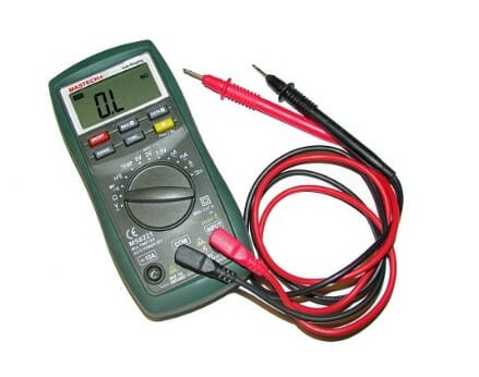
There is no continuity if the test power is not detected. It should display 1 or OL (open loop) on the screen.
Note: A specific continuity mode is not available on all multimeters. However, you can still conduct a circuit continuity test if your multimeter does not have a particular continuity test mode.
You may use the resistance mode instead. This is usually indicated as the symbol ohm (Ω). Remember to configure the dial to the lowest setting.
Voltage Test
When analyzing the performance of electrical and electronic circuits or trying to figure out why a circuit isn't working as it should, you'll need to monitor the various voltage levels.
- Connect the black probe to your multimeter's COM port. Insert the red probe into the VΩmA port.
- Change the dial on your multimeter to DC voltage mode (represented by a V with a straight line or the sign ⎓).
- The positive terminal should contact the red probe, whereas you should also contact the negative terminal with the black probe.
- Then, wait for the result.
Understanding Voltage Test Results
Although most multimeters aren't auto-ranging, you'll have to manually select the appropriate range for the voltage you'll be measuring.
The maximum voltage it can measure is listed for each position on the dial. Use the 20-volt level, for example, if you intend to measure over 2 volts but less than 20.

Proceed with the highest setting if you're unsure. However, you may not receive a precise estimation if your range is set too high. On the other hand, the multimeter just reads 1 or OL if you set the range too low, signifying that it is overloaded or out of reach. This won't harm the multimeter, but we'll need to increase the range on the dial.
Flipping the probes will not hurt you; it will only result in a negative reading.
Resistance Test
The power flow applied to the circuit is used to compute resistance. When current flows to the circuit under test, a voltage is produced (resistance). You can use it to figure out how well a circuit or component works. The lesser the current flow, the more ideal the resistance, and vice versa.
Keep in mind that you'll be testing the complete circuit's resistance. If you wish to test a single component, such as a resistor, do so without being soldered in place.
Read along as I usher you on how to perform a resistance test using a multimeter:
- Verify that no power is flowing through the circuit or component you want to test first. Take any batteries, turn them off, and disconnect them from the wall.
- Connect the black probe to your multimeter's COM port. Insert the red probe into the VΩmA port.
- Configure your multimeter to the resistance function and turn it on.
- One probe should be attached to the end of the circuit or the component you want to test.
Understanding Resistance Test Results
Resistance is non-directional; thus, it doesn't matter which probe travels where.
The multimeter just reads 1 or OL if you set the range low, signifying that it is overloaded or out of range. This won't affect the multimeter, but we'd have to increase the range on the dial.
Another possibility is that the network or device you're testing does not have continuity, which means it has infinite resistance. A non-continuous connection will always indicate 1 or OL on a resistance test.
Safety Tips
It's simple to measure continuity, but don't let its simplicity get in the way of your safety. To protect yourself from shocks and your multimeter from harm, follow these guidelines:
- When using a multimeter, always wear high-quality protective hand gloves.
- While measuring continuity, always turn off the device.
- If continuity testing is a routine activity for you, make sure you replace your multimeter's batteries on a regular basis. The buzzing sound reduces the batteries' power more quickly. (2)
For other learning guides for testing using a multimeter, you may check the list below;
- How to measure amps with a multimeter
- How to find a short circuit with a multimeter
- How to measure DC voltage with a multimeter
References
(1) electric charge – https://www.livescience.com/53144-electric-charge.html
(2) batteries' power – http://www2.eng.cam.ac.uk/~dmh/ptialcd/
battery/index.htm
Source: https://toolsweek.com/how-to-check-continuity-with-a-multimeter/
0 Response to "How Do You Use a Multimeter to Check a Circuit for Continuity"
Postar um comentário